Optimizing STL File Quality for Superior 3D Prints
Ever wonder why your perfectly smooth CAD designs sometimes turn into visibly faceted, low-resolution 3D prints? This common issue isn’t typically your 3D printer’s fault. The culprit often lies in how your 3D model is translated into an STL file, the standard format for 3D printing. Understanding and optimizing your STL file’s quality is crucial for achieving the smooth curves, dimensional accuracy, and fine details your designs deserve.
This guide will walk you through the essential aspects of STL files, focusing on the critical export parameters that dictate print quality. By mastering these settings, you’ll ensure your digital designs translate seamlessly into physical objects, making your 3D printing journey more successful and your prints more professional.
What is an STL File?
The STL file format, an acronym for STereoLithography (and sometimes referred to as Standard Triangle Language or Standard Tessellation Language), has been the industry standard for 3D printing since its creation by 3D Systems in 1987. It was originally developed for stereolithography technology, a form of additive manufacturing.
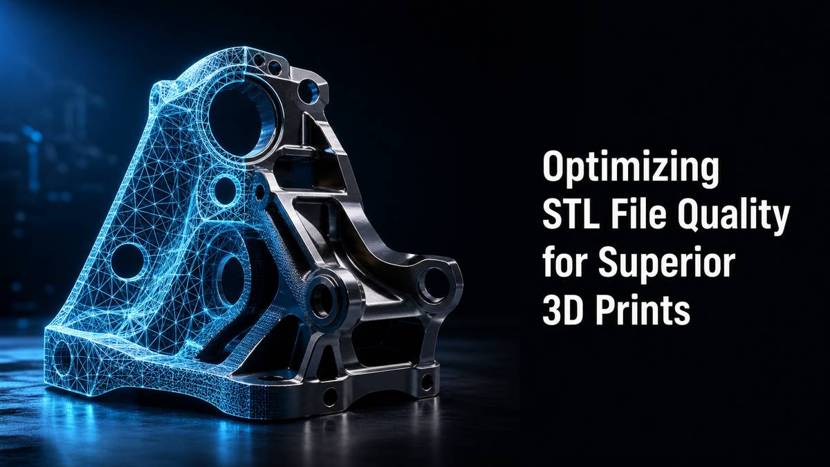
An STL file represents the surface geometry of a 3D model using a series of linked triangles, or tessellations. Imagine wrapping your 3D object in a mesh of tiny triangles. The more complex the design and the finer the detail, the more triangles are used to approximate its surfaces. Each triangle stores information about its vertices’ coordinates, essentially describing the outer shell of your object.
It’s important to note that STL files describe only the surface geometry. They do not carry information about color, texture, or material properties. This characteristic makes them lightweight but also limits their use for more complex visual applications where color and texture are vital.
Why STL File Quality Matters for 3D Printing
The quality of your STL file directly impacts the final output of your 3D printer. A low-quality STL file, characterized by a coarse mesh (fewer, larger triangles), will result in:
- Faceted Surfaces: Smooth curves in your original CAD model will appear as distinct flat surfaces, compromising the aesthetic and functional intent of your design.
- Reduced Dimensional Accuracy: The triangulated approximation might not precisely match your CAD model, leading to inaccuracies in dimensions and fit.
- Loss of Detail: Fine features and sharp edges can be blurred or lost if the mesh isn’t fine enough to capture them.
Conversely, a high-quality STL file accurately represents your CAD model’s geometry, leading to smoother surfaces, higher dimensional accuracy, and better detail retention in the final 3D print.
Understanding Key STL Export Parameters
When exporting your 3D model from CAD software to an STL file, you’ll typically encounter several critical parameters that control the mesh quality. Adjusting these settings correctly is fundamental to achieving high-quality prints.
1. Chordal Tolerance (Chordal Deviation)
Chordal tolerance defines the maximum allowable distance between the surface of your original CAD model and the surface of the triangulated STL mesh. Think of it as how far the flat triangle surface is allowed to deviate from the true curve of your design.
- Smaller Chordal Tolerance: Results in a denser mesh with more, smaller triangles. This leads to a higher-resolution STL file that more accurately represents curved surfaces, making them appear smoother in the final print. However, it also increases file size and can slow down slicing.
- Larger Chordal Tolerance: Results in a coarser mesh with fewer, larger triangles. This creates a lower-resolution STL file, leading to visible faceting on curved surfaces but a smaller file size.
Recommendation: A common starting point for a good balance between quality and file size is 0.1 mm (\”0.004 inches\”).
2. Angular Tolerance (Angular Deviation/Normal Deviation)
Angular tolerance specifies the maximum angle allowed between the normal vectors of adjacent triangles in the mesh. A normal vector is perpendicular to the surface of a triangle, indicating its orientation.
- Smaller Angular Tolerance: Forces the software to create more triangles at sharper curves and transitions, ensuring that adjacent triangles align more closely to the original surface. This results in smoother transitions and better definition of curved features. Similar to chordal tolerance, a smaller value increases resolution and file size.
- Larger Angular Tolerance: Allows for a greater angle difference between adjacent triangles, leading to a coarser approximation of curved surfaces and potentially visible \”hard edges\” where smooth transitions should be.
Recommendation: A recommended angular tolerance setting is 1 degree.
3. Minimum Triangle Side Length (Optional)
Some CAD software offers an optional setting for the minimum triangle side length. This parameter prevents the generation of excessively small triangles, which can occur on very small features or extremely sharp angles.
- Setting a minimum side length can help prevent issues with certain slicers or printers that struggle with extremely small geometric elements. While it can slightly reduce the absolute finest detail, it often improves file stability and processing.
Recommendation: If available, a setting of 0.1 mm (\”0.004 inches\”) is often suitable.
4. Binary vs. ASCII Format
STL files can be exported in two formats:
- Binary: This format stores information in a compact, unreadable binary code. Binary STL files are significantly smaller in file size and are the preferred format for practical 3D printing applications.
- ASCII: This format stores information as human-readable text. ASCII STL files are much larger than binary files, making them less efficient for typical 3D printing workflows.
Recommendation: Always export your STL files in binary format to optimize file size and processing speed.
Balancing Mesh Quality and File Size
While aiming for the highest possible resolution seems ideal, there’s a practical trade-off: file size. A very high-resolution STL file (with extremely small chordal and angular tolerances) can contain tens or hundreds of millions of triangles, leading to:
- Excessively Large File Sizes: Files exceeding 20 MB can significantly slow down the slicing process in your 3D printing software (e.g., Bambu Studio, OrcaSlicer, Cura, PrusaSlicer).
- Memory Issues: Large files can strain your computer’s resources during design, export, and slicing.
- Longer Processing Times: Slicing software takes much longer to process a very dense mesh.
Recommended Workflow for STL Export
- Start with Recommended Settings: Begin by exporting your CAD geometry with the following parameters:
- Binary STL format
- Chordal Tolerance/Deviation: 0.1 mm [\”0.004 in\”]
- Angular Tolerance/Deviation: 1 deg
- Minimum Triangle Side Length: 0.1 mm [\”0.004 in\”] (if applicable)
- Check File Size: After export, examine the resulting STL file size.
- Adjust if Necessary:
- If the file size is greater than 20 MB: Consider increasing the values for chordal and angular tolerance (e.g., to 0.15mm and 2 degrees) to reduce the number of triangles until the file size drops below 20 MB. Prioritize reducing file size if processing speed is critical.
- If your model still shows excessive faceting: You can try decreasing the values for chordal and angular tolerance (e.g., to 0.05mm and 0.5 degrees) for finer detail. However, always monitor the file size and try to keep it below the 20 MB threshold for optimal performance.
The goal is to find the sweet spot where your print quality is excellent, but your file size remains manageable for efficient slicing and printing.
General Steps for Exporting STL Files from CAD Software
While specific menu paths vary between CAD software like Fusion 360, SolidWorks, or FreeCAD, the general process for exporting an STL and adjusting its quality parameters is similar:
- Open your CAD Model: Load the 3D model you wish to print into your CAD software.
- Access Export/Save As Option: Look for options like \”File\” > \”Export,\” \”Save As,\” or \”Export Mesh.\”
- Select STL Format: Choose \”STL\” or \”.stl\” as the file type.
- Locate Mesh/Output Options: In the export dialog, find settings related to \”Options,\” \”Resolution,\” \”Mesh Quality,\” or \”Output Settings.\” This is where you’ll find the chordal tolerance, angular tolerance, and possibly minimum triangle side length.
- Adjust Parameters: Input your desired values for chordal and angular tolerance based on the recommendations above. Ensure \”Binary\” is selected for the output format.
- Preview (if available): Some software allows you to preview the triangulated mesh before exporting. Use this to visually inspect for faceting.
- Export: Save the STL file to your desired location.
- Verify: Open the STL file in a viewer or your slicer (e.g., Bambu Studio) to confirm the mesh quality and file size.
Troubleshooting Common STL Issues
- Faceted Prints: If your prints have visible flat spots where there should be smooth curves, your STL was likely exported with a too-coarse resolution (high chordal or angular tolerance). Re-export with smaller tolerance values.
- Slow Slicing/Software Lag: If your slicer takes an unusually long time to load or process your STL, or if your computer slows down significantly, your STL file is likely too large. Re-export with slightly increased chordal and angular tolerance values to reduce the mesh density and file size.
- Missing Features/Holes: Ensure your original CAD model is a \”solid\” body with no open edges or non-manifold geometry. STL files represent surfaces, so a non-watertight model can cause issues in slicing.
Conclusion
Designing for 3D printing isn’t just about creating an amazing CAD model; it’s also about preparing that model correctly for the printing process. Understanding and appropriately setting your STL export parameters – specifically chordal tolerance, angular tolerance, and opting for binary format – is a fundamental skill for any 3D printer user.
By carefully balancing mesh quality with file size, you can avoid common pitfalls like faceted prints and slow processing times, ensuring your 3D printer produces parts that accurately reflect your design intent with smooth, professional finishes. Invest a little time in these settings, and you’ll see a significant improvement in the quality of your 3D printed objects.