Mastering SLS 3D Printing: Process, Benefits, and Design Essentials
Selective Laser Sintering (SLS) 3D printing stands out as a powerful additive manufacturing process for producing highly functional, durable plastic parts. Whether you’re developing rapid prototypes or creating end-use components for low-volume production, understanding SLS technology is crucial for achieving optimal results.
Unlike common desktop 3D printing methods like FDM, SLS utilizes a laser to fuse powdered material, eliminating the need for support structures and allowing for intricate geometries previously impossible. This guide delves into the core mechanics of SLS, its significant advantages, the materials it uses, and critical design considerations to help you avoid common pitfalls and maximize the potential of this industrial-grade technology.
How SLS 3D Printing Works: The Powder Bed Fusion Process
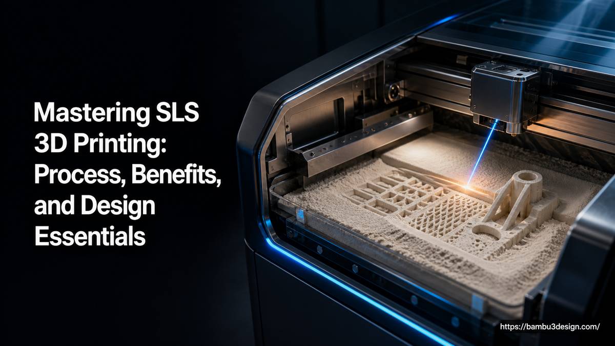
SLS is a powder bed fusion technique that builds parts layer by layer within a contained chamber. The process relies on a laser to selectively sinter (fuse) polymer powder, creating solid cross-sections that accumulate to form a three-dimensional object. Here’s a breakdown of the typical workflow:
- Powder Deposition: A roller or recoater spreads a thin layer of fine polymer powder (e.g., nylon) onto a build platform within a heated build chamber.
- Laser Sintering: A CO2 laser selectively scans and heats the powder layer according to the digital model’s cross-section. The laser’s energy fuses the powder particles together, solidifying them into a dense, solid material.
- Platform Lowering: Once a layer is complete, the build platform descends slightly (typically 0.1 to 0.15 mm).
- Repeat Layers: Steps 1-3 are repeated, with new powder layers deposited and selectively sintered on top of the previous ones, gradually building the part from the bottom up.
- Cooling: After all layers are sintered, the entire powder bed, containing the encapsulated parts, cools down slowly within the chamber. This controlled cooling process helps to minimize warping and internal stresses.
- Breakout and De-powdering: Once cooled, the block of unsintered powder, with the printed parts embedded within, is moved to a breakout station. Parts are manually extracted from the powder bed, and most loose powder is brushed off.
- Post-processing: The remaining residual powder is typically removed using bead blasting. Additional finishing steps like dyeing, smoothing, or coating can be applied depending on the application requirements.
Crucially, the surrounding unsintered powder acts as a natural support structure for the parts during printing, allowing for complex geometries and hollow designs without the need for additional support materials.
Key Benefits of SLS 3D Printing Technology
SLS offers several distinct advantages that make it a preferred choice for various demanding applications:
- Exceptional Strength and Durability: SLS parts, particularly those made from nylon, exhibit strong mechanical properties, high toughness, and resistance to impact and chemicals, making them suitable for functional end-use applications.
- Complex Geometries and Intricate Designs: The self-supporting nature of the powder bed allows for the creation of intricate internal channels, thin walls, and complex interlocking features that would be challenging or impossible with other manufacturing methods.
- No Support Structures Required: Unlike FDM or SLA, SLS doesn’t need dedicated support material, simplifying post-processing, reducing material waste, and allowing for greater design freedom.
- Material Versatility: While nylon-based materials are most common, SLS can be adapted to process a variety of plastic, metal, ceramic, and glass powders, though plastics are most prevalent for prototyping and functional parts.
- Rapid Prototyping and Production: SLS can produce accurate prototypes and functional production parts quickly, often within a few days, eliminating time-consuming tooling processes for low-volume batches.
- Cost-Effectiveness for Small Batches: For low-volume production and customized parts, SLS can offer a more economical solution compared to traditional manufacturing methods that require expensive molds or tooling.
Common Materials for SLS 3D Printing
The most widely used and versatile material for SLS 3D printing is Nylon, primarily PA12. Its balance of strength, flexibility, and chemical resistance makes it ideal for a broad range of applications.
- Nylon PA12: This is the workhorse of SLS, known for its excellent mechanical properties, high durability, and resistance to environmental factors. It’s perfect for strong, functional parts and prototypes.
- Nylon PA12 Glass-Filled: For applications requiring even greater stiffness, heat deflection, and dimensional stability, glass-filled nylon provides enhanced performance. The glass particles reinforce the nylon matrix, increasing its rigidity.
These engineering-grade materials contribute significantly to SLS’s capability to produce robust components.
Critical Design Considerations for SLS 3D Printing
Even with the flexibility of SLS, certain design oversights can lead to warping, weak areas, or increased costs. Adhering to specific guidelines during the design phase is crucial for successful prints. Here are top design mistakes to avoid:
1. Ignoring Minimum Wall Thickness
Walls that are too thin can warp, crack, or fail during the sintering process or post-processing. SLS builds parts layer by layer by fusing powder, and unsupported thin walls are particularly vulnerable to thermal stress and mechanical forces during de-powdering.
- Guideline:
- For rigid Nylon PA12: 1.0–1.5 mm minimum.
- For Nylon PA12 Glass-Filled: 1.5–2.0 mm recommended.
- For tall, unsupported structures, increase to 2.5 mm or more.
- Tip: When designing fine details or snap-fit features, reinforce them with gradual transitions rather than sharp changes in thickness to distribute stress more effectively.
2. Overlooking Drainage or Escape Holes in Hollow Parts
Hollow models printed with SLS will trap unsintered powder inside if there are no pathways for it to escape. This trapped powder adds unnecessary weight, increases material costs, and can cause issues during post-processing or subsequent treatments like vapor smoothing.
- Guideline:
- Include at least two escape holes, ideally on opposite sides to facilitate powder removal.
- Recommended diameter: 6–10 mm minimum.
- Larger parts may require multiple escape holes for thorough powder evacuation.
- Tip: Utilize rounded transitions at the edges of escape holes instead of sharp corners. This can reduce stress concentrations and improve airflow for better cleaning.
3. Designing Features Too Close Together
SLS powder requires a certain clearance between adjacent or moving parts to prevent them from fusing together during the sintering process. This is especially critical for assemblies, hinges, or components designed to move freely after printing.
- Guideline:
- Minimum clearance between moving parts: 0.5 mm.
- For tight tolerances or parts that will undergo post-processing (e.g., dyeing, coating): 0.6–0.8 mm is advisable.
- Avoid nested or interlocking parts unless specifically designed with sufficient clearance for SLS.
- Tip: Always perform virtual test-fits of critical assemblies in your CAD software before committing to a physical print batch.
4. Forgetting About Part Orientation and Warping
While SLS doesn’t require support structures in the traditional sense, part orientation within the build chamber still impacts final part quality, particularly strength and surface finish. Large flat areas or long, thin features are more prone to slight warping due to thermal stress during the sintering and cooling process.
- Guideline:
- Avoid orienting long, thin parts with extensive flat bases parallel to the build platform.
- Incorporate ribbing or internal lattice structures into large, flat surfaces to enhance stiffness and minimize deformation.
- Consider segmenting very large parts into smaller sections and joining them post-print if a monolithic structure is difficult to achieve without warping.
- Tip: If your design has critical functional surfaces or aesthetic requirements, communicate this when preparing your model, as optimized orientation can improve accuracy and surface quality in those areas.
Conclusion
SLS 3D printing is a sophisticated and highly capable additive manufacturing technology, offering unparalleled freedom for creating strong, complex, and functional parts. Its ability to produce durable nylon components without dedicated support structures makes it an ideal choice for both rapid prototyping and low-volume production of end-use parts.
By understanding the fundamental SLS process and, critically, by adhering to essential design principles—such as maintaining minimum wall thicknesses, incorporating drainage holes for hollow sections, ensuring adequate feature clearance, and carefully considering part orientation—designers can harness the full power of SLS to achieve high-quality, reliable printed components.