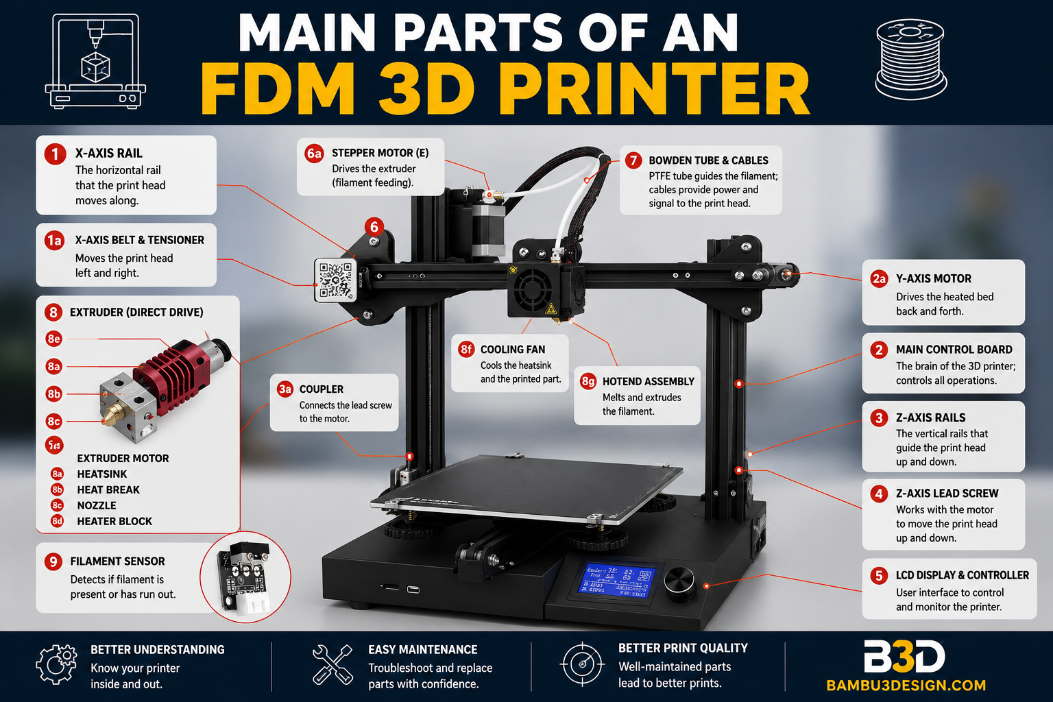
In this article, we will examine the main parts of an FDM 3D printer. FDM 3D printers are built using different mechanical systems and various platforms. Each platform has its own advantages and unique features, and it cannot be said that all FDM 3D printers have exactly the same components. However, they all use filament melting technology and ultimately operate in the same way. Therefore, it can be said that they share similar parts, with more than 70% of the components being common among them.
Introduction to the Main Parts of an FDM 3D Printer
The image shown above is an example of a commercial FDM 3D printer called the Ender, which is based on the Prusa platform. It is a good example for exploring the overall structure and understanding the fundamentals of a 3D printer. This printer is a Cartesian-type printer and features X, Y, and Z axes. Let’s take a closer look at the different sections of this printer.
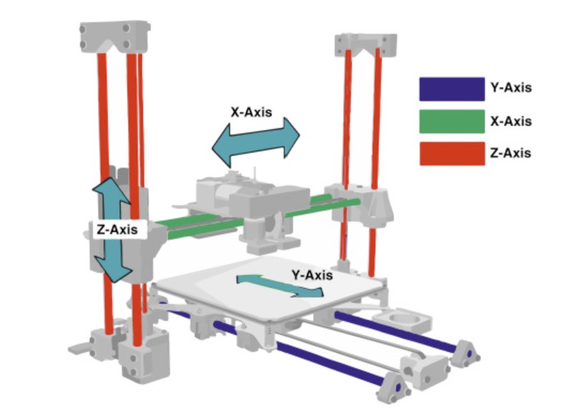
X, Y, and Z Axes in the Anatomy of a 3D Printer
The purpose of a 3D printer is to create a physical object from a designed model. To produce three-dimensional objects, movement is required along three coordinate axes. Different 3D printers may have different mechanical designs and structures compared to the example shown above, but the principles, rules, and naming conventions remain the same. If you stand in front of a 3D printer, the axes are defined as follows:
1. X-Axis in a 3D Printer
Movement to the left and right takes place along the X-axis. A stepper motor (1a) is used to drive motion along this axis. The printer’s hotend assembly moves along the X-axis.
2. Y-Axis in a 3D Printer
Movement forward and backward takes place along the Y-axis. A stepper motor (2a) is responsible for movement along this axis. The print bed is mounted on the Y-axis.
3. Z-Axis in a 3D Printer
Movement up and down takes place along the Z-axis. Stepper motors (3a) are typically installed on both sides of the frame columns, and movement is achieved through lead screws or threaded rods.
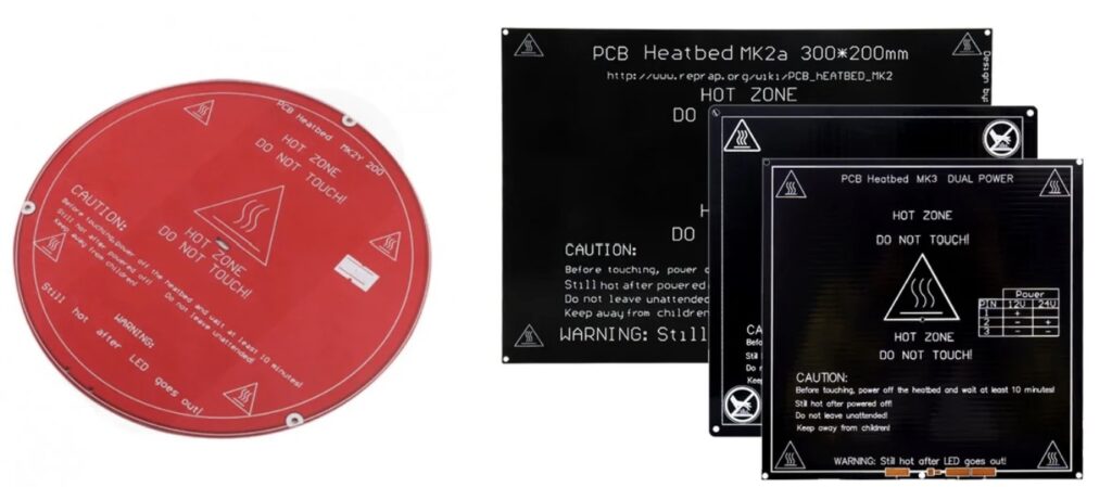
4. Heated Bed
One of the main parts of a 3D printer is the Heated Bed, also known as the print bed. This is the surface on which the final object is built. Heated beds are commonly made from 3 mm aluminum plates or PCB-based heating elements. The bed can typically reach temperatures of up to 100°C. Heated beds are available in different sizes such as 10×10 cm, 20×20 cm, 30×20 cm, and 30×30 cm. They can be circular, rectangular, or square, depending on the printer platform.
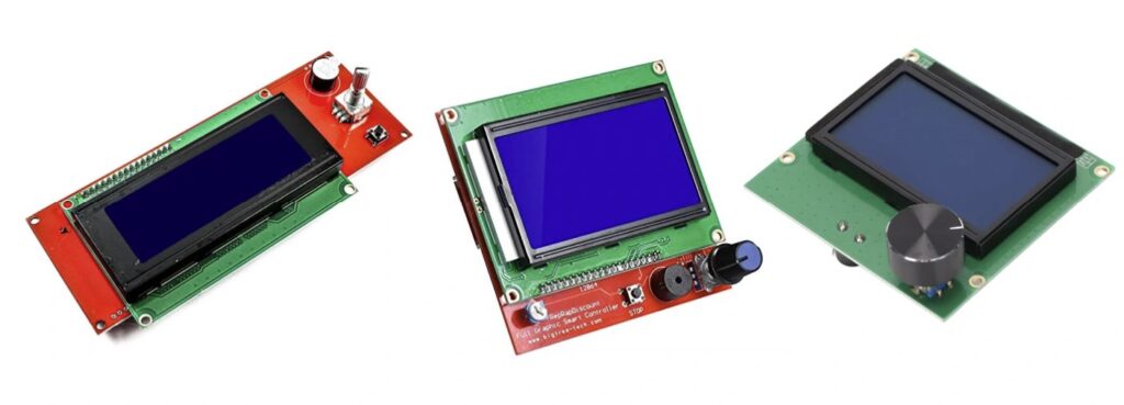
5. Display and Printer Controller
The printer is controlled and configured through this section. Next to the display, there is usually a slot for a memory card, which is used to transfer the final 3D model file (typically in STL format) to the printer. The display is connected to the printer’s main processor and allows users to monitor printing progress, view system information, and adjust printer settings when necessary.
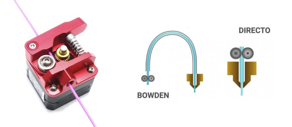
6. Extruder
The extruder pushes filament into the hot section so that it can be melted and extruded through the nozzle. A stepper motor (6a) and a drive gear work together to feed the filament at a controlled rate. Various extruder designs exist, with the MK8 being one of the most common. Extruders may be mounted on the printer frame, with filament guided through a tube to the hotend—this setup is called a Bowden system. The printer shown in the image uses this method. Another configuration is the Direct Drive system, where the extruder is mounted directly on top of the hotend.
7. PTFE Tube
The PTFE tube is used to transfer filament from the extruder to the hotend. This tube is only present in Bowden-style printers. Direct Drive printers do not require a PTFE tube between the extruder and hotend.
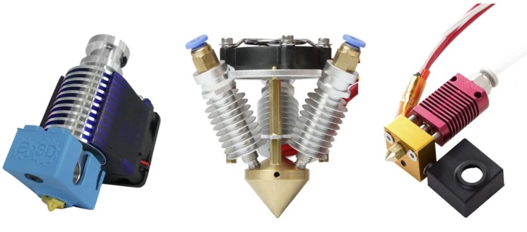
8. Hotend
The hotend is one of the most important parts of an FDM 3D printer. Its job is to melt the filament before extrusion. The hotend consists of several subcomponents:
8a. Nozzle
The nozzle heats up and melts the filament. At the tip of each nozzle is a circular opening ranging from 0.1 mm to 2 mm in diameter, through which molten filament is deposited onto the print bed. The standard nozzle size is 0.4 mm.
8b. Heater Block
The heater block connects the nozzle, heating element, and temperature sensor while also helping maintain thermal stability.
8c. Heater Cartridge
A heater cartridge is required to heat the nozzle and hotend assembly. It fits into the heater block and can generate temperatures of up to 300°C.
8d. Thermistor
The temperature produced by the heater cartridge must be monitored and controlled. The printer’s processor reads temperature data from the thermistor and adjusts heating accordingly. The thermistor is installed inside the heater block.
8e. Heat Sink
The heat sink is the part of the hotend that must remain cool to prevent heat from traveling upward from the heater block. Ideally, heat should remain confined to the melting zone. Without a heat sink, filament above the hotend could soften prematurely and cause jams.
8f. Heat Sink Cooling Fan
This fan cools the heat sink and the filament passing through it, helping prevent filament jams.
8g. Part Cooling Fan
The part cooling fan rapidly cools freshly extruded material. Not all printers include this fan, and its use depends on the material being printed. For example, PLA benefits from active cooling, which improves print quality, while ABS may warp if cooled too aggressively.
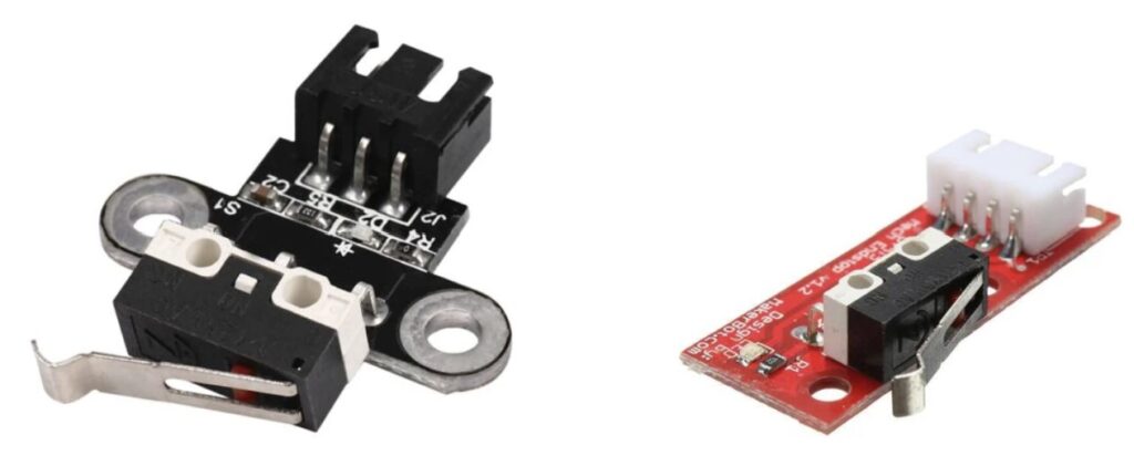
9. End Stops
End stops are simple micro-switches that activate when pressed. A printer typically requires end stops on the X and Y axes to establish the zero position of each axis. Once an end stop is triggered, motor movement is halted to prevent overtravel.
10. Additional Components of a 3D Printer
These components are optional. A printer can function without them, but they can improve convenience, accuracy, and reliability.
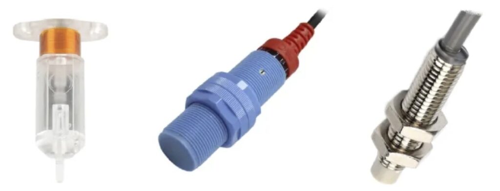
a. Auto-Level Sensor
As mentioned in Section 9, end stops are used to define the limits of the X and Y axes. For the Z-axis, a more precise sensor—often inductive or mechanical—is commonly used. This sensor can automatically adjust the distance between the nozzle and the heated bed or assist in leveling the entire print surface.
b. Filament Runout Sensor
This sensor detects when filament has run out and pauses the printing process, allowing the user to replace the filament before continuing the print.