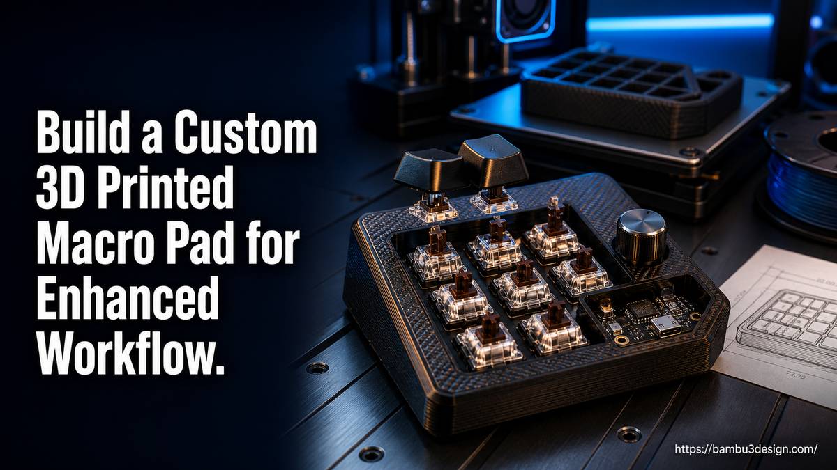
Are you constantly performing repetitive key combinations, navigating complex software menus, or struggling to control your smart home devices efficiently? A custom 3D printed macro pad offers a versatile and cost-effective solution to streamline your digital interactions and enhance productivity.
Unlike off-the-shelf options, a DIY macro pad allows for complete customization in design, functionality, and aesthetic. Whether you’re a gamer, a CAD designer, a programmer, or simply a smart home enthusiast, building your own macro pad provides an engaging project and a practical tool tailored to your specific needs.
This guide will walk you through the essential components, design considerations, 3D printing techniques, and software configurations required to create your own functional and personalized macro pad.
What is a Macro Pad?
A macro pad is essentially a small, specialized keyboard with a limited number of keys, often ranging from 2 to 20. Each key can be programmed to execute a macro—a sequence of commands or actions—with a single press. These actions can include:
- Complex Key Combinations: Simulating
Ctrl+Alt+Deleteor application-specific shortcuts. - Launching Programs: Opening frequently used software or specific files.
- Running Scripts: Automating tasks in your operating system or applications.
- Media Control: Play, pause, skip, or volume adjustments.
- Smart Home Control: Toggling lights, adjusting brightness, or activating scenes.
- 3D Printer Control: Sending Klipper commands for movement, heating, or macros.
Macro pads offer immense possibilities for customization, making them popular desktop accessories among DIY enthusiasts and professionals alike.
Why Build a Custom 3D Printed Macro Pad?
The appeal of a DIY 3D printed macro pad extends beyond simple functionality. Here are compelling reasons to undertake this project:
- Customization: Design the exact number of keys, layout, and form factor that suits your workflow. Integrate rotary encoders for fine control (e.g., brightness, volume) or OLED displays for feedback.
- Cost-Effectiveness: Commercial smart controllers or specialized macro pads can be expensive. By sourcing individual electronic components and 3D printing the enclosure, you can build a high-quality device for a fraction of the price.
- Enhanced Productivity: Map frequently used commands to single buttons, significantly speeding up tasks in CAD software, video editing, programming, or gaming.
- Learning Experience: It’s a challenging yet manageable project that introduces you to electronics, CAD design, 3D printing, and firmware programming—a perfect stepping stone for more complex maker endeavors.
- Personal Expression: Choose your filament colors, keycap styles, and display themes to create a device that perfectly matches your desk setup and personality.
Essential Components for Your Macro Pad
Building a macro pad requires a blend of electronic components and a custom 3D printed enclosure. Here’s a breakdown of what you’ll typically need:
1. Microcontroller (The Brain)
This is the core of your macro pad, interpreting button presses and sending commands. Common choices include:
- ESP32-based boards: Excellent for smart home integration due to built-in Wi-Fi. Boards like Adafruit’s QT Py ESP32 are compact and reliable.
- RP2040-based boards: Popular for general macro pads and 3D printer control. Examples include Raspberry Pi Pico, RP2040 Zero (smaller form factor), or Seeed Studio XIAO RP2040. These are widely available and cost-effective.
- Arduino boards: Suitable for simpler macro pad projects, especially for beginners.
2. Input Devices
- Mechanical Switches: Standard Cherry MX-style switches are common, offering satisfying tactile feedback and durability. Consider hotswap sockets for easy switch replacement and experimentation.
- Push Buttons: Simpler, often illuminated buttons can be used, particularly for industrial or Klipper control applications.
- Rotary Encoders: Ideal for continuous adjustments like volume, brightness, or scrolling. Many encoders include a built-in push switch for additional functionality.
3. Output Devices (Optional)
- OLED Displays: Small screens can show active macros, light scenes, or system information, adding a professional touch.
- RGB LEDs: Provide visual feedback, status indicators, or aesthetic lighting.
4. Printed Circuit Board (PCB) or Wiring
- Hand-wiring: For simple prototypes, you can directly wire switches to the microcontroller. This is beginner-friendly but less robust.
- Custom PCB: For a cleaner, more durable, and potentially shippable product, a custom PCB is recommended. Tools like KiCad or Autodesk Eagle can be used for design, and services like PCBWay can fabricate them.
5. Miscellaneous Hardware
- Keycaps: Choose standard or custom keycaps to fit your switches and aesthetic.
- Mounting Hardware: M3 screws are commonly used to mount components into 3D printed bosses.
- Wires, Solder, USB Cable: For connecting components and powering the device.
Designing and 3D Printing the Enclosure
The 3D printed enclosure houses all your electronics and provides the ergonomic interface for your macro pad. Careful design and material selection are crucial.
CAD Software Options
- Fusion 360: A powerful, parametric CAD tool suitable for detailed designs, including features like mounting bosses and complex shapes. Excellent for creating modular systems.
- Tinkercad: A free, browser-based, and beginner-friendly CAD program. Ideal for simple enclosures and learning basic 3D modeling concepts. Many tutorials are available for creating macro pad cases.
Choosing Your Filament
The choice of filament depends on the macro pad’s intended environment and desired aesthetics:
- PLA: A versatile and easy-to-print material, suitable for most desktop applications. Prusament Woodfill offers unique wood-like aesthetics.
- ASA: If your macro pad will be placed inside a 3D printer enclosure that gets warm, or in any environment exposed to higher temperatures or UV light, ASA is a better choice than PLA due to its heat resistance and durability.
Printing Considerations
- Multi-Material Printing: Printers like the Prusa XL or those equipped with an MMU3 (Multi-Material Unit) can print enclosures with multiple colors or materials for aesthetic appeal, minimizing filament waste.
- Single-Material Printing: Even with a single-tool machine, multi-color designs are possible by manually swapping filaments at specific layers, though this can lead to more waste.
- Dimensional Accuracy: Expect several iterations when printing to achieve the perfect friction fit for components or precise screw holes. Fine-tuning your slicer settings (e.g., Bambu Studio, PrusaSlicer) is essential.
Wiring and Assembly
Hand-Wired Approach
For simpler designs or prototypes, you can hand-wire the switches directly to the microcontroller. This involves soldering wires from each switch to specific input pins on your board. While functional, it can be time-consuming and prone to issues if not carefully executed.
Custom PCB Approach
Designing and ordering a custom PCB simplifies wiring significantly. The PCB provides dedicated solder pads for all components, making assembly cleaner and more reliable. This is recommended for designs with many keys or if you plan to create multiple units.
General Assembly Steps (varies by design):
- Print Enclosure: 3D print the top and bottom parts of your macro pad case.
- Mount Switches/Buttons: Secure switches into the top plate of the enclosure. If using M3 screws into plastic, ensure your CAD design includes appropriate mounting bosses.
- Wire Components: If hand-wiring, connect switches, rotary encoders, and displays to the microcontroller. If using a PCB, solder all components onto the board.
- Enclose Electronics: Carefully place the assembled electronics into the bottom enclosure part.
- Final Assembly: Secure the top and bottom enclosure parts, often with friction fit or small screws.
Programming Your Macro Pad
Once assembled, your macro pad needs firmware to function. The choice of firmware depends on the microcontroller and intended use.
Firmware for PC Control
For controlling your computer, popular firmware options include:
-
QMK (Quantum Mechanical Keyboard) Firmware: A powerful, open-source firmware known for its extensive customization capabilities. It requires some coding knowledge but offers unparalleled flexibility.
-
VIAL: A QMK fork that includes a graphical user interface (GUI) for configuring keymaps, making it more accessible without deep coding.
-
Arduino IDE: Suitable for basic macro pads, especially if your microcontroller is Arduino-compatible. It can be used for MIDI macro pads.
-
KMK Keyboard Firmware: A Python-based firmware, offering a different programming approach for those familiar with Python.
Firmware for 3D Printer Control (Klipper)
If you’re building a macro pad specifically for a Klipper-powered 3D printer, the process involves flashing Klipper firmware to a secondary microcontroller (like an RP2040 board) and configuring it to communicate with your Klipper host (e.g., Raspberry Pi).
Steps for Klipper Macro Pad Setup (using RP2040):
- Connect to Klipper Host: Use SSH (e.g., PuTTY, PowerShell) to access your Raspberry Pi.
- Navigate to Klipper Directory:
cd klipper - Configure Firmware: Run
make menuconfig. Change the architecture toRP2040(or your specific chip). Leave other options default. - Build Firmware: Type
make. This compiles the firmware. Note the output file name. - Transfer Firmware: Use a tool like WinSCP to copy the
.uf2firmware file from your Pi to your computer. - Flash Microcontroller: Connect your RP2040 board to your computer while holding its BOOT button. It will appear as a removable drive. Drag and drop the
.uf2file onto it. The board should eject automatically. - Connect to Pi: Unplug the RP2040 from your computer and connect it to your Klipper host (Raspberry Pi) via USB.
- Identify Serial Port: In SSH, run
ls /dev/serial/by-id/*. Locate the entry for your RP2040 board (it will containRP2040in the name). This is the serial path you’ll add to yourprinter.cfgfile. - Configure
printer.cfg: Add a[mcu your_macro_pad_name]section to your Klipper config, specifying theserial:path identified in the previous step, and define your buttons and corresponding Klipper macros.
Advanced Features and Customization
Beyond basic button functions, you can integrate advanced features to make your macro pad even more versatile:
- Modular Designs: Experiment with magnetic connectors to create a system where different macro pad modules (e.g., 6-key, rotary encoder module, joystick module) can snap together to form various layouts.
- Layer Switching: Implement different “layers” or profiles for your macro pad, allowing the same physical buttons to perform different functions depending on the active application or context. An OLED display can indicate the current layer.
- Detachable Switch Plates: Design your enclosure with a detachable switch plate, allowing you to easily swap out switches or customize layouts without disassembling the entire unit.
Conclusion
Building a custom 3D printed macro pad is a rewarding project that combines electronics, CAD design, and 3D printing into a practical tool. From enhancing your productivity in complex software to simplifying smart home controls or streamlining your 3D printing workflow, a personalized macro pad puts essential commands right at your fingertips. With readily available components and open-source firmware, the journey from concept to a fully functional device is within reach for any maker. Embrace the challenge, customize it to your heart’s content, and transform your digital interaction experience.